Rendering Real-Time 3D Before GPUs
How I built real-time 3D rendering on a slow 486 with only 256 colors in VGA Mode 13h, using fixed-point math, palette quantization, matcap-style Phong lighting, and x86 assembly.
Ben Houston • • 13 min read
In early 1997, while I was in high school, I built a software renderer that was capable of per-pixel Phong lighting, texture mapping with bump mapping in real-time on a 1993-era 486 DX2 50Mhz computer (yeah, it wasn't the latest technology but it is what my Dad had in the house.) I taught myself most of the techniques from BBS tutorials, early internet writeups, demo-scene source releases, and Michael Abrash's writing.
I recently went back through the original codebase. This post is a write-up of how I solved the problem of getting high-quality real-time 3D results on hardware with no GPU, a slow FPU, and a 256-color display.
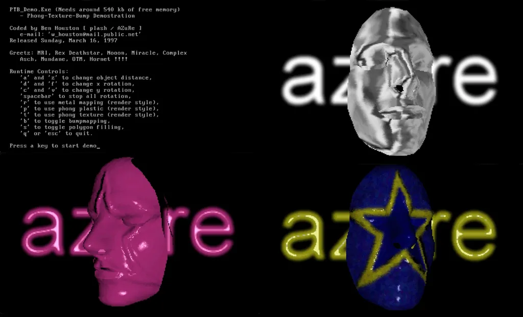
I wrote the engine in C++ with Borland C++ 4.0. Wherever the inner loops needed to be fast, I dropped into hand-written x86 assembly through Borland C++'s integrated TASM capabilities.
The full source is here GitHub as 3DMaskDemo1997.
VGA Mode 13h and a Software Double Buffer#
I used VGA Mode 13h, the straightforward 320x200 256-color mode that you could enable with a single BIOS interrupt.
This was a 16-bit DOS program, so it lived in the standard conventional-memory world of at most 640 KB. That limit shaped everything from how I stored assets to how large I could make the off-screen buffers and lookup tables.
The mode switch was as simple as:
// Switch the VGA card into 320x200 with 256 colors.
asm mov ax, 0x13
asm int 0x10
Mode 13h did not give me a second hardware page to flip between, so I built my own double buffering in software. Each frame rendered into an off-screen buffer in conventional memory. Once the frame was done, I copied only the dirty rectangle into video memory using a hand-written x86 block copy.
That gave me the flicker-free animation I wanted without moving to Mode X and its unchained page-flipping setup. I built a software substitute for hardware page flipping rather than hardware page flipping itself.
This is the dirty-rectangle copy routine:
void copyrect ( word source, word dest, recttype rect )
{
    int copywidth, skipwidth, copyheight, startoffset;

    // Round the rectangle to dword boundaries so the copy loop
    // can use movsd efficiently.
    copywidth = ((rect.r + 3) >> 2) - (rect.l >> 2);
    skipwidth = 320 - (copywidth << 2);
    copyheight = rect.b - rect.t + 1;
    startoffset = rect.t * 320 + ((rect.l >> 2) << 2);

    // Copy only the dirty rectangle from the virtual screen to video memory.
    asm push ds
    asm mov ds, [source]
    asm mov es, [dest]
    asm mov si, [startoffset]
    asm mov di, si
    asm mov dx, [skipwidth]
    asm mov bx, [copyheight]
lineloop:
    asm mov cx, [copywidth]
    asm rep movsd
    asm add di, dx
    asm add si, dx
    asm dec bx
    asm jnz lineloop
    asm pop ds
}
Fixed-Point Math and Rotation#
The 486 could do floating-point math, but not quick enough for the frame rates I wanted, so I used fixed-point arithmetic instead. There was a significant cost to converting between integers and floating point on the 486 in addition to the raw floating-point arithmetic cost, so keeping the inner loops mostly in integer math was a practical win.
Instead of using the entire range of a 16-bit integer for whole numbers, I reserved some of those bits for the fractional part. Then I could use ordinary integer add, subtract, and multiply instructions, as long as I kept track of where the implied decimal point lived. In a few places I did need 32 bit intermediates for multiplications.
For the rotation code, 256 represented 1.0, so multiplying a coordinate by a trig value also multiplied it by 256. The >> 8 shifted the result back down by 256, restoring the intended scale after the fixed-point multiply. In floating point, rotating around the X axis is just:
and the fixed-point code below is that same matrix multiply, with
and
pre-scaled by 256 and the >> 8 undoing the scale afterward.
Different parts of the renderer used different fixed-point scales:
8fractional bits for the rotation math6fractional bits for rasterizer screen-space coordinates14fractional bits for some texture and lighting coordinate intermediates before scaling them back down
I tuned the precision per subsystem instead of using one format across the whole engine.
For example, here is the actual rotation setup from transformvertices():
// Compute the trig values once per frame and store them in
// 8-bit fixed-point form.
xcos = (int) ( cos ( (float)xrotation / MAX_ANGLE * M_PI * 2 ) * 256 );
xsin = (int) ( sin ( (float)xrotation / MAX_ANGLE * M_PI * 2 ) * 256 );
ycos = (int) ( cos ( (float)yrotation / MAX_ANGLE * M_PI * 2 ) * 256 );
ysin = (int) ( sin ( (float)yrotation / MAX_ANGLE * M_PI * 2 ) * 256 );

for ( loop = 0; loop < totalvertices; loop ++ ) {
    // Load the object-space vertex.
    x = objectvertex[loop].x;
    y = objectvertex[loop].y;
    z = objectvertex[loop].z;

    // Rotate around X and shift away the fixed-point scale.
    // The trig values are scaled by 256, so >> 8 divides by 256 again.
    ytemp = y;
    ztemp = z;
    y = ( ytemp * xcos - ztemp * xsin ) >> 8;
    z = ( ytemp * xsin + ztemp * xcos ) >> 8;

    // Rotate around Y the same way.
    xtemp = x;
    ztemp = z;
    x = ( xtemp * ycos - ztemp * ysin ) >> 8;
    z = ( xtemp * ysin + ztemp * ycos ) >> 8;
}
Plastic Rendering via Phong Light Map#
Plastic mode was the simplest of the three renderers. It used a single material color and a procedurally generated light map based on the Phong illumination model. That fit directly in the palette of 256 colors.
I also wanted to avoid lighting only at the vertices and then interpolating the result across the triangle, as in Gouraud shading, because specular highlights tend to look soft or disappear entirely that way. Instead I wanted something closer to Phong shading, meaning effectively per-pixel lighting, so I precomputed the illumination into a lookup texture and sampled it per pixel during rasterization.
In modern terms, this Phong light map was also a rough predecessor to a MatCap: instead of evaluating the lighting equation in the inner loop, I looked up a precomputed shading result from a 2D map using the rotated normal.
I computed the lighting values from an actual Phong illumination model, roughly:
where
is the angle between the surface normal and the light,
and
are the diffuse and specular colors,
,
, and
are the diffuse, specular, and ambient weights, and
is the specular falloff exponent. In code:
real phongillumination ( real diffusecolor, real specularcolor,
                    real lightcolor,  real ambientcolor, real theta )
{
    real phongcolor;

    // Diffuse term.
    phongcolor =  ( K_DIFFUSE * diffusecolor * cos( theta ));
    if ( theta < M_PI / 4 )
    {
        // Specular highlight near the center of the lobe.
        phongcolor += ( K_SPECULAR * specularcolor * pow( cos( theta * 2 ), K_FALLOFF ));
    }
    // Light intensity and attenuation.
    phongcolor *= ( K_ATTENUATION * lightcolor );
    // Ambient floor.
    phongcolor += ( ambientcolor * K_AMBIENT * diffusecolor );

    // Clamp to the normalized range before converting to palette space.
    if ( phongcolor > 1.0 )
        phongcolor = 1.0;
    else if ( phongcolor < 0.0 )
        phongcolor = 0.0;

    return phongcolor;
}
I then used an arcsine lookup table to convert the rotated vertex normals into u and v coordinates for that lighting map:
// Convert the rotated normal components into light-map coordinates.
for ( loop = -128; loop < 128; loop ++ )
    asinlookup[loop+128] = 255.0 * asin ( loop / 128.0 ) / M_PI + 127;

screenvertex[loop].u = asinlookup[(xint+256) >> 1];
screenvertex[loop].v = asinlookup[(yint+256) >> 1];
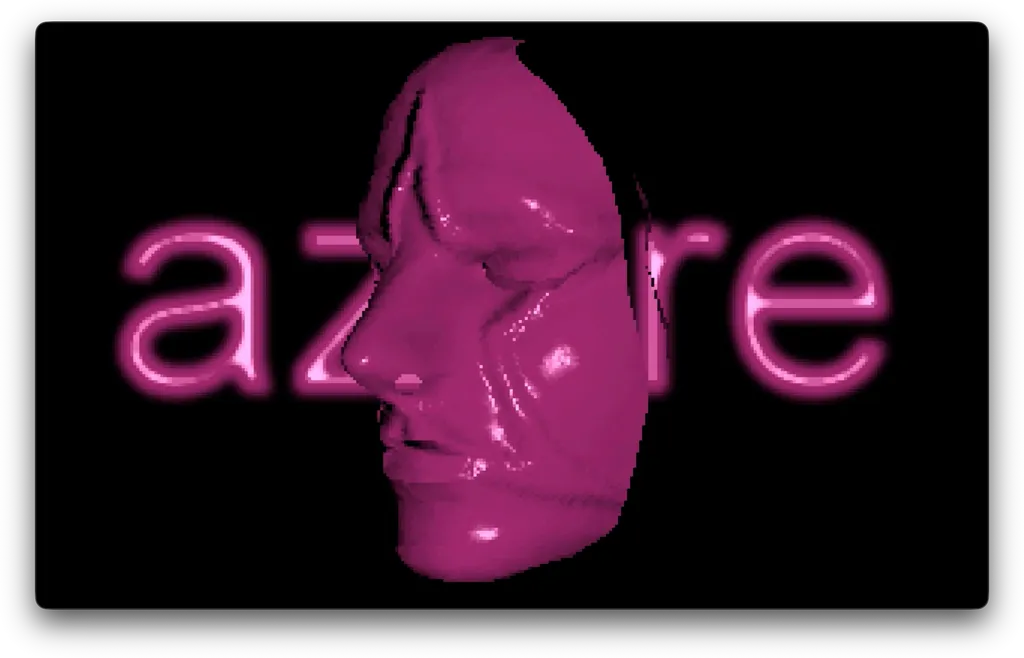
Plastic mode used a procedural Phong light map and fit directly in the palette.
Texture Mapping via Color Quantization#
Texture mode combined a diffuse texture with the Phong light map. That created too many colors to fit directly into Mode 13h's 256-color palette.
The input space was:
32texture palette entries128lighting shades32 x 128 = 4096lit colors
This is the mode where quantization became necessary. Plastic mode did not need it because it was a single lit material color ramp. Texture mode did need it because every texture color had to be multiplied by every lighting level.
What quantization did here was compress those thousands of candidate lit colors down to a much smaller palette that VGA hardware could actually display, while trying to preserve the overall appearance as well as possible. An adaptive palette builder such as median cut is useful for this because it analyzes the actual set of input colors and spends more of the limited palette entries in the regions of color space where the image data is densest or varies the most.
I generated those 4,096 lit colors up front by running each texture color through the Phong lighting function at each shade level:
for ( palcolor = 0; palcolor < 32; palcolor ++ ) {
    // Start from one of the 32 texture colors.
    tclr = texturepal[palcolor];

    for ( shade = 0; shade < 128; shade ++ ) {
        // Convert the shade level into the corresponding incident angle.
        incedent = ( (real)(128 - ( shade + 1 )) / 128 ) * ( M_PI / 2 );

        // Light that texture color under this angle.
        temp.r = 63 * phongillumination ( tclr.r/63.0, 1.0, LIGHT_R, AMBIENT_R, incedent );
        temp.g = 63 * phongillumination ( tclr.g/63.0, 1.0, LIGHT_G, AMBIENT_G, incedent );
        temp.b = 63 * phongillumination ( tclr.b/63.0, 1.0, LIGHT_B, AMBIENT_B, incedent );

        // Add the result to the set the quantizer will compress.
        basecolor[numbasecolors] = temp;
        numbasecolors++;
    }
}
I quantized that space down to 256 colors with a median-cut palette builder:
void processcolorcube ( colortype min, colortype max, int level )
{
    int deltar, deltag, deltab, longest;
    colortype color, minsplit, maxsplit;

    // Shrink the cube to the colors that actually exist inside it.
    shrinkcolorcube ( &min, &max );

    deltar = max.r - min.r;
    deltag = max.g - min.g;
    deltab = max.b - min.b;

    if ( level == 0 ) {
        // At the leaf, emit one palette entry from the cube midpoint.
        color.r = min.r + ( deltar / 2 );
        color.g = min.g + ( deltag / 2 );
        color.b = min.b + ( deltab / 2 );

        optimalpal[palcount] = color;
        palcount++;
    }
    else {
        // Split along the axis with the widest color range.
        if ( deltab >= deltar && deltab >= deltag )
            longest = COLOR_BLUE;
        else if ( deltar >= deltag && deltar >= deltab )
            longest = COLOR_RED;
        else
            longest = COLOR_GREEN;

        // Cut at the median population point, then recurse.
        determinedivision ( min, max, longest, &minsplit, &maxsplit );

        level--;
        processcolorcube ( min, minsplit, level );
        processcolorcube ( maxsplit, max, level );
    }
}
At runtime, the per-pixel cost of combining texture and lighting became one array read:
// texel selects the diffuse color, shade selects the light level,
// and the table returns the nearest palette entry.
index = shadetable[texel*128 + shade];
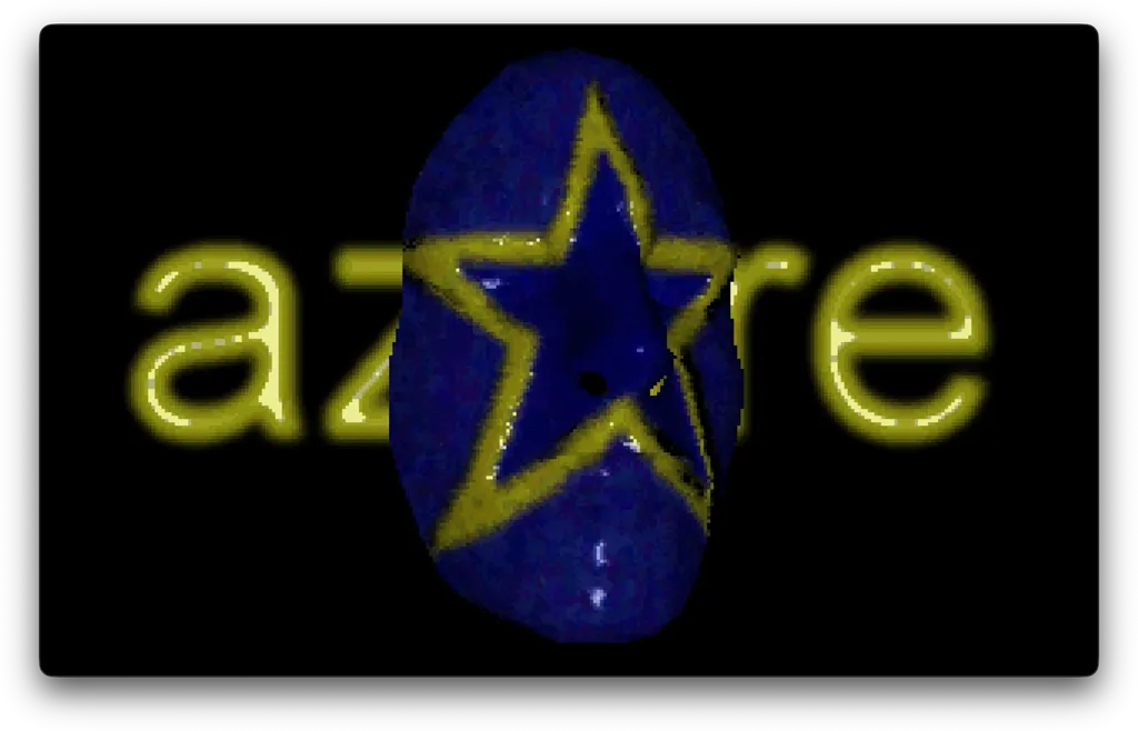
Texture mode combined the diffuse texture with the quantized Phong lighting result.
Shared Triangle Rasterization#
Triangles were rasterized with a DDA, a digital differential analyzer approach. I sorted each triangle top to bottom, walked the left and right edges to get start and end x positions for each scanline, and then ran a horizontal fill routine across each scanline.
All three renderers shared this rasterization structure. The textured path had the busiest inner loop because it had to sample both the diffuse texture and the lighting map, combine them through the shade table, and write the final palette index to the framebuffer.
This is the core of envirotexturetriangle():
do {
    // Sample the diffuse texture using interpolated texture coordinates.
    asm mov es, word ptr [texturemap]
    asm mov ah, byte ptr [a+1]
    asm mov al, byte ptr [b+1]
    asm mov di, ax
    asm mov al, es:[di]
    asm mov [texel], al

    // Sample the Phong light map using the interpolated normal coordinates.
    asm mov es, word ptr [enviromap]
    asm mov ah, byte ptr [u+1]
    asm mov al, byte ptr [v+1]
    asm mov di, ax
    asm mov al, es:[di]
    asm mov [shade], al

    // Combine texture and lighting through the precomputed shade table.
    index = shadetable[texel*128 + shade];

    // Write the final palette index to the framebuffer.
    asm mov es, [destscreen]
    asm mov di, [poffset]
    asm mov al, [index]
    asm mov es:[di], al

    // Step all interpolants to the next pixel.
    poffset ++;
    a += dadx;  b += dbdx;
    u += dudx;  v += dvdx;
    width --;
} while ( width > 0 );
Metallic Rendering via Reflection Mapping#
Metallic mode used the same basic environment-mapping idea as the plastic Phong mode, but instead of a procedurally generated light map it used an artist-made reflection image loaded from disk. In modern terms, it was a reflective MatCap.
The palette was a straight grayscale ramp, and the reflection map provided the shape of the highlight and the sense of reflective metal:
for ( int loop = 0; loop < 256; loop ++ ) {
    // Build a grayscale palette so the reflection map controls the look.
    reflectpal[loop].r = loop>>2;
    reflectpal[loop].g = loop>>2;
    reflectpal[loop].b = loop>>2;
}

// Load the artist-authored reflection image into the environment map.
loadreflectmap ();
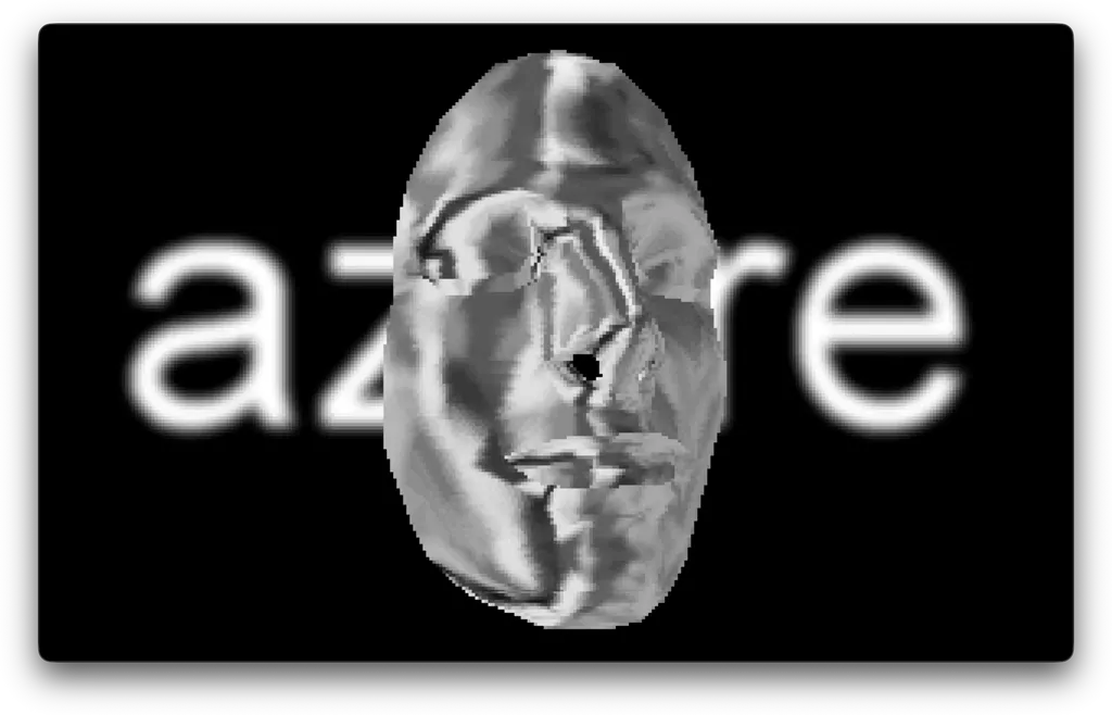
Metallic mode used a reflection map in place of the procedural Phong light map.
Adding Bump Mapping#
The bump mapping approximated surface detail by perturbing the lighting lookup.
For each pixel, I sampled a height map at four offset positions to estimate local slope. That slope was then added directly to the coordinate used to sample the lighting map. In other words, I was perturbing the lookup into the shading function, not constructing a true perturbed 3D normal and relighting from that.
This is the core of the bump-mapped inner loop from envirobumptexturetriangle():
// Sample the height map one pixel forward and backward in both directions.
a1 = ((a + dadx) & 0xff00) + ((b + dbdx) >> 8);
a2 = ((a - dadx) & 0xff00) + ((b - dbdx) >> 8);
b1 = ((a + dady) & 0xff00) + ((b + dbdy) >> 8);
b2 = ((a - dady) & 0xff00) + ((b - dbdy) >> 8);

asm xor ax, ax
asm mov es, [bumpmap]
// Horizontal height difference.
asm mov di, [a1]
asm mov al, es:[di]
asm mov [ah1], ax
asm mov di, [a2]
asm mov al, es:[di]
asm mov [ah2], ax
// Vertical height difference.
asm mov di, [b1]
asm mov al, es:[di]
asm mov [bh1], ax
asm mov di, [b2]
asm mov al, es:[di]
asm mov [bh2], ax

// Add the local slope to the light-map lookup coordinates.
bmpu = ah1 - ah2 + (u >> 8);
bmpv = bh1 - bh2 + (v >> 8);
This is an emboss-style bump mapping technique. It approximates a perturbed normal without paying the cost of computing one explicitly.
One subtle point here is that only the lighting lookup gets perturbed. The diffuse texture coordinates stay untouched. That is the correct behavior. Bump maps should change the apparent shading of the surface, not slide the albedo texture around underneath it.
What This Was#
This was a very period-specific set of solutions. 3D graphics accelerators like the Voodoo serie, dedicated graphics memory, and CPU improvements like fast floating point obsoleted pretty much all of these techniques.
On the bright side, this work did land me my first job in the industry. Sir-Tech Canada hired me that summer to help with their transition from a 2D game studio to 3D.
This post was written in response to a question from Mauve re: what did I actually do in the demo scene.